
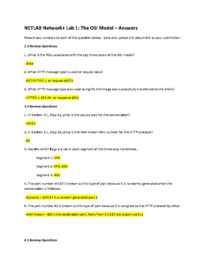
- Information
- AI Chat
8.2.1.5 Lab - Designing and Implementing a VLSM Addressing Scheme
Introduction to Networks (Tech 65)
San José State University
Recommended for you

Students also viewed
- apuntes de la asignatura tecnologia y modernizacion
- 2.9.2 Lab - Basic Switch and End Device Configuration
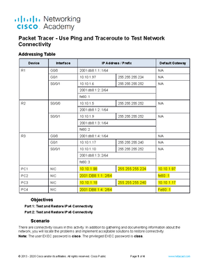
- Netlab - Testing Network Connectivity with Ping and Traceroute
- 13.2.7 Packet Tracer - Use Ping and Traceroute to Test Network Connectivity
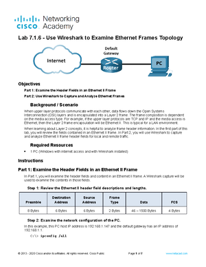
- 7.1.6 Lab - Use Wireshark to Examine Ethernet Frames
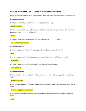
- Network+ LAB 2 Answer Sheet
Preview text
Topology
Objectives
Part 1: Examine Network Requirements Part 2: Design the VLSM Address Scheme Part 3: Cable and Configure the IPv4 Network
Background / Scenario
Variable Length Subnet Mask (VLSM) was designed to avoid wasting IP addresses. With VLSM, a network is subnetted and then re-subnetted. This process can be repeated multiple times to create subnets of various sizes based on the number of hosts required in each subnet. Effective use of VLSM requires address planning. In this lab, use the 172.16.128/17 network address to develop an address scheme for the network displayed in the topology diagram. VLSM is used to meet the IPv4 addressing requirements. After you have designed the VLSM address scheme, you will configure the interfaces on the routers with the appropriate IP address information. Note : The routers used with CCNA hands-on labs are Cisco 1941 Integrated Services Routers (ISRs) with Cisco IOS Release 15(4)M3 (universalk9 image). Other routers and Cisco IOS versions can be used. Depending on the model and Cisco IOS version, the commands available and output produced might vary from what is shown in the labs. Refer to the Router Interface Summary Table at the end of this lab for the correct interface identifiers. Note : Make sure that the routers have been erased and have no startup configurations. If you are unsure, contact your instructor.
Required Resources
3 routers (Cisco 1941 with Cisco IOS software, Release 15(4)M3 universal image or comparable) 1 PC (with terminal emulation program, such as Tera Term, to configure routers) Console cable to configure the Cisco IOS devices via the console ports Ethernet (optional) and serial cables, as shown in the topology
Windows Calculator (optional)
Part 1: Examine Network Requirements
In Part 1, you will examine the network requirements to develop a VLSM address scheme for the network displayed in the topology diagram using the 172.16.128/17 network address. Note : You can use the Windows Calculator application and the ipcalc IP subnet calculator to help with your calculations.
Step 1: Determine how many host addresses and subnets are available.
How many host addresses are available in a /17 network? 32766 What is the total number of host addresses needed in the topology diagram? 31506 How many subnets are needed in the network topology? 9
Step 2: Determine the largest subnet.
What is the subnet description (e. BR1 G0/1 LAN or BR1-HQ WAN link)? HQ G0/0 LAN How many IP addresses are required in the largest subnet? 16000 What subnet mask can support that many host addresses? /18 or 255.255. How many total host addresses can that subnet mask support? 16382 Can you subnet the 172.16.128/17 network address to support this subnet? Yes What are the two network addresses that would result from this subnetting? 172.16.128/ 172.16.192/ Use the first network address for this subnet.
Step 3: Determine the second largest subnet.
What is the subnet description? HQ G0/1 LAN How many IP addresses are required for the second largest subnet? 8000 What subnet mask can support that many host addresses? /19 or 255.255. How many total host addresses can that subnet mask support? 8190 Can you subnet the remaining subnet again and still support this subnet? Yes What are the two network addresses that would result from this subnetting? 172.16.192/ 172.16.240/ Use the first network address for this subnet.
Step 4: Determine the next largest subnet.
What is the subnet description? BR1 G0/1 LAN How many IP addresses are required for the next largest subnet? 4000 What subnet mask can support that many host addresses?
What are the two network addresses that would result from this subnetting? 172.16.252/ 172.16.254/ Use the first network address for this subnet.
Step 8: Determine the subnets needed to support the serial links.
How many host addresses are required for each serial subnet link? 2 What subnet mask can support that many host addresses? /30 or 255.255. a. Continue subnetting the first subnet of each new subnet until you have four /30 subnets. Write the first three network addresses of these /30 subnets below. 172.16.254/ 172.16.254/ 172.16.254/ b. Enter the subnet descriptions for these three subnets below. HQ – BR1 Serial Link HQ – BR2 Serial Link BR1 – BR2 Serial Link
Part 2: Design the VLSM Address Scheme
Step 1: Calculate the subnet information.
Use the information that you obtained in Part 1 to fill in the following table.
Subnet Description
Number of Hosts Needed
Network Address /CIDR
First Host Address
Broadcast Address HQ G0/0 16,000 172.16.128/18 172.16.128 172.16. HQ G0/1 8,000 172.16.192/19 172.16.192 172.16. BR1 G0/1 4,000 172.16.224/20 172.16.224 172.16. BR1 G0/0 2,000 172.16.240/21 172.16.240 172.16. BR2 G0/1 1,000 172.16.248/22 172.16.248 172.16. BR2 G0/0 500 172.16.252/23 172.16.252 172.16. HQ S0/0/0 – BR1 S0/0/0 2 172.16.254/30 172.16.254 172.16. HQ S0/0/1 – BR2 S0/0/1 2 172.16.254/30 172.16.254 172.16. BR1 S0/0/1 – BR2 S0/0/0 2 172.16.254/30 172.16.254 172.168.
Step 2: Complete the device interface address table.
Assign the first host address in the subnet to the Ethernet interfaces. HQ should be given the first host address on the Serial links to BR1 and BR2. BR1 should be given the first host address for the serial link to BR2. Device Interface IP Address Subnet Mask Device Interface
HQ
G0/0 172.16.128 255.255.192 16,000 Host LAN G0/1 172.16.192 255.255.224 8,000 Host LAN S0/0/0 172.16.254 255.255.255 BR1 S0/0/ S0/0/1 172.16.254 255.255.255 BR2 S0/0/
BR
G0/0 172.16.240 255.255.248 2,000 Host LAN G0/1 172.16.224 255.255.240 4,000 Host LAN S0/0/0 172.16.254 255.255.255 HQ S0/0/ S0/0/1 172.16.254 255.255.255 BR2 S0/0/
BR
G0/0 172.16.252 255.255.254 500 Host LAN G0/1 172.16.248 255.255.252 1,000 Host LAN S0/0/0 172.16.254 255.255.255 BR1 S0/0/ S0/0/1 172.16.254 255.255.255 HQ S0/0/
Part 3: Cable and Configure the IPv4 Network
In Part 3, you will configure the three routers using the VLSM address scheme that you developed in Part 2
Router Interface Summary Table
Router Interface Summary Router Model Ethernet Interface #1 Ethernet Interface #2 Serial Interface #1 Serial Interface # 1800 Fast Ethernet 0/ (F0/0)
Fast Ethernet 0/ (F0/1)
Serial 0/0/0 (S0/0/0) Serial 0/0/1 (S0/0/1)
1900 Gigabit Ethernet 0/ (G0/0)
Gigabit Ethernet 0/ (G0/1)
Serial 0/0/0 (S0/0/0) Serial 0/0/1 (S0/0/1)
2801 Fast Ethernet 0/ (F0/0)
Fast Ethernet 0/ (F0/1)
Serial 0/1/0 (S0/1/0) Serial 0/1/1 (S0/1/1)
2811 Fast Ethernet 0/ (F0/0)
Fast Ethernet 0/ (F0/1)
Serial 0/0/0 (S0/0/0) Serial 0/0/1 (S0/0/1)
2900 Gigabit Ethernet 0/ (G0/0)
Gigabit Ethernet 0/ (G0/1)
Serial 0/0/0 (S0/0/0) Serial 0/0/1 (S0/0/1)
Note : To find out how the router is configured, look at the interfaces to identify the type of router and how many interfaces the router has. There is no way to effectively list all the combinations of configurations for each router class. This table includes identifiers for the possible combinations of Ethernet and Serial interfaces in the device. The table does not include any other type of interface, even though a specific router may contain one. An example of this might be an ISDN BRI interface. The string in parenthesis is the legal abbreviation that can be used in Cisco IOS commands to represent the interface.
8.2.1.5 Lab - Designing and Implementing a VLSM Addressing Scheme
Course: Introduction to Networks (Tech 65)
University: San José State University


- Discover more from:


Recommended for you
Students also viewed
- apuntes de la asignatura tecnologia y modernizacion
- 2.9.2 Lab - Basic Switch and End Device Configuration
- Netlab - Testing Network Connectivity with Ping and Traceroute
- 13.2.7 Packet Tracer - Use Ping and Traceroute to Test Network Connectivity
- 7.1.6 Lab - Use Wireshark to Examine Ethernet Frames
- Network+ LAB 2 Answer Sheet