- Information
- AI Chat
VCE unit 3 and 4 physics cheat sheet
physics cheat sheet
Subject
Physics- Unit 4
46 Documents
Students shared 46 documents in this course
School
High School - Australia
Academic year: 2020/2021
Uploaded by:

0followers
3Uploads
236upvotes
Recommended for you


Was this document helpful?
VCE unit 3 and 4 physics cheat sheet
Subject: Physics- Unit 4
46 Documents
Students shared 46 documents in this course
Was this document helpful?

The induced EMF of moving conductor in magnetic field
A conductor initial in magnetic field doesn’t have induced
current because no change in magnetic flux. However, when it
starts moving magnetic flux increase significantly, then doesn’t
change and then slightly decrease until 0.
𝜺=𝑩𝒍𝒗
𝜀: induced emf (V)
B: magnetic field
strength (T)
l: length of conductor
v: velocity of
conductor
Faraday’s Law of induction
Doesn’t matter whether the coil or magnet are changed if it
is a change in magnetic flux there is induced EMF.
Farday states if the flux through “N” number of loops of a coil
changes from 𝜙𝑖𝑛𝑡𝑖𝑎𝑙 to 𝜙𝑓𝑖𝑛𝑎𝑙then induced EMF/current.
𝜺=−𝑵𝚫𝝓
𝚫𝒕 =−𝑵𝝓𝒇𝒊𝒏𝒂𝒍−𝝓𝒊𝒏𝒕𝒊𝒂𝒍
𝒕𝒇𝒊𝒏𝒂𝒍−𝒕𝒊𝒏𝒊𝒕𝒂𝒍
If the ends of a coil are connected to circuit, then a current will
flow:
𝐼=𝜀
𝑡
N: number of loops/turns
Lenz’s Law
1. Don’t confuse induced current and induced current action.
2. When induced current action (magnet) try to move in/move
out a coil or solenoid. Initially coil or solenoid don’t have
induced current but because of induced current action this
will generate induced current in coil or solenoid. The
direction of this induced current will oppose direction of
induced current action
Tips: negative sign indicate anticlockwise direction of
induced current.
1. Δ𝜙=−;𝜙𝑓𝑖𝑛𝑎𝑙 <𝜙𝑖𝑛𝑡𝑖𝑎𝑙: clockwise: 𝜀=+
2. Δ𝜙=+;𝜙𝑓𝑖𝑛𝑎𝑙 >𝜙𝑖𝑛𝑡𝑖𝑎𝑙: anticlockwise
𝜀=−
The direction of induced current by changing area
1. For a magnetic field get into a page
When S.A B:out of page Anticlockwise
When S.A B: into the page Clockwise
2. For a magnetic field go out page
When S.A B: into the page Clockwise
When S.A B: out of page Anticlockwise
AC Generator/Alternator
• Main different is slip ring: allow the coil rotating without
tangling. Produce AC voltages which can be either positive
or negative
• NOTE: GRAPH of EMF is NEGATIVE DERIVATIVE of
magnetic flux
DC generator
For Dc generator
because of
commutator reverse
direction of current
every half turn. So no
negative area
Peak, Peak-Peak&RMS
Root mean square voltage is the
equivalent steady voltage DC supply
which provide the same power
𝑉𝑟𝑚𝑠 =𝑣𝑝𝑒𝑎𝑘
√2
𝐼𝑟𝑚𝑠 =𝐼𝑝𝑒𝑎𝑘
√2
𝑉𝑝𝑒𝑎𝑘−𝑝𝑒𝑎𝑘 =2𝑉𝑝𝑒𝑎𝑘
𝑃𝑟𝑚𝑠 =𝐼𝑟𝑚𝑠𝑉𝑟𝑚𝑠 =1
2𝑣𝑝𝑒𝑎𝑘𝐼𝑝𝑒𝑎𝑘
𝑃𝑝𝑒𝑎𝑘 =2𝐼𝑟𝑚𝑠𝑉𝑟𝑚𝑠
Factors:
speedvoltage f period
speedvoltagefperiod
Transformers
Application of electromagnetic
induction, metal core increase
efficiently. Size is independent. Only
work for AC voltages.
𝑁𝑝
𝑁𝑠=𝑉𝑝
𝑉𝑠=𝐼𝑠
𝐼𝑝
𝑁𝑠>𝑁𝑝=Step up
𝑁𝑠<𝑁𝑝=Step down
Factors
𝑁𝑝 by X factor
𝑉𝑝 will by X factor
𝐼𝑝will by X factor
Transmission Loss
𝐼 𝑤𝑖𝑟𝑒𝑠 =𝑃𝑖𝑛
𝑉𝑖𝑛
𝑉 𝑙𝑜𝑠𝑠 =𝐼 𝑤𝑖𝑟𝑒𝑠𝑅 𝑤𝑖𝑟𝑒𝑠
𝑉 𝑜𝑢𝑡 =𝑉𝑖𝑛− 𝑉 𝑙𝑜𝑠𝑠
𝑃𝐿𝑜𝑠𝑠 =𝐼𝑤𝑖𝑟𝑒𝑠2𝑅 𝑤𝑖𝑟𝑒𝑠
𝑃 𝑜𝑢𝑡 =𝑃𝑖𝑛− 𝑃 𝑙𝑜𝑠𝑠
𝑃 𝑜𝑢𝑡 =𝑉𝑜𝑢𝑡 −𝐼
Transformer allow same power
to transmitted at higher voltage,
higher voltage lower current,
lower current means lower
power losses in transmissions.
Waves
Transverse wave: oscillations are
perpendicular to wave direction(light)
Longitudinal wave: oscillations are parallel to
the wave direction (sound)
Graphs:
Doppler efect
Doppler effect is produced when
the source of a wave moves with
respect to the observed causing an
apparent shift in frequency for the
observer
Relative motion Toward
frequency
Relative motion away
frequency
Reflection of waves
Superposition of waves
Resonance
When an object creates an external force and
vibrates another object at a frequency that
exactly matches one of the natural
frequencies. This object then absorbs energy
and have twice of amplitude
Standing Waves
ONE CLOSED END&ONE OPEN END
(Start: Node; End: Antinode)
𝝀𝒏=𝟒𝒍
𝟐𝒂−𝟏= 𝟒𝒍
𝒏
𝒇𝒏=𝒏𝒗
𝟒𝒍=(𝟐𝒂−𝟏)𝒗
𝟒𝒍 =𝒏𝒇𝟏
n: number of harmonic (odd number only)
a: number of antinodes
l: length of string
TWO CLOSED ENDS
(Start&end: Nodes)
𝝀𝒃=𝟐𝒍
𝒃
𝒇𝒃=𝒃𝒗
𝟐𝒍=𝒃𝒇𝟏
b: number of antinodes and number of
harmonics
TWO OPEN ENDS
(Start&end: antinode)
𝝀𝒄=𝟐𝒍
𝒄
𝒇𝒄=𝒄𝒗
𝟐𝒍=𝒄𝒇𝟏
c: number of nodes
𝑓1 : frequency of first harmonic
Diffraction of Wave
Number of diffractions =𝝀
𝑤 ; 𝝀
𝑤≥1:
significant diffraction
Light as Wave
Light is transverse wave or electromagnetic wave. In
this model, magnetic field travel parallel to wave
direction and electric field travel perpendicular to
wave direction. Electric field travel perpendicular to
magnetic field.
Power doesn’t affect by transformer
Electromagnetic Wave
In vacuum, all magnetic wave travel at “c”
Coherent&Incoherent
Incoherent: doesn’t contain same frequency
and doesn’t not have wavelengths that are in
phase with one another (LED)
Coherent: Waves are in step or in phase
(LAZER)
Interference
Constructive (bright band/antinodal
/maxima/ 2waves inphase
𝒑.𝒅=𝒏𝝀
Destructive (Dark band/nodal/minima/2
waves outphase )
𝒑.𝒅=(𝒏+𝟏
𝟐)𝝀
Fringe separation
∆𝑥=𝑛𝜆𝐿
𝑑
∆𝑥: distance between any two bright
band or dark band. These are equal
L: distance from slits to screen
d: slit separation
n: number of bright band
if it is a dark band then (
𝒏+𝟏
𝟐)
Single slit diffraction of light
dsin𝜃=𝑛𝜆=𝑑𝑦
𝐿
d: slit separation
L: distance from slits to screen
Y: distance from centre to minimum
point or n.
Smaller d greater intensity fridge
separation increase appear further
on screen
Refraction of light
When light change medium, speed will
change due to wavelength change,
Frequency doesn’t change. It will cause
refraction. 𝑛=𝑐
𝑣
𝑛1𝑣1=𝑛2𝑣2
n: refractive index
v: speed of light in medium
Snell’s Law
n1: refractive index of medium coming from
n2: refractive index of medium going to
Dispersion
White light is combination of different colours of light.
Different colour of light has different wavelength and
travel refract differently.
Lower frequency: less refract
Higher frequency: more refract
Polarisation
Occur to transverse wave. Allowed wave to vibrate in
one direction. Light show electric field perpendicular
to magnetic field Vertical filter: block magnetic
field horizontal filter:block electric field
Ratio
𝑛2
𝑛1=sin𝜃1
sin𝜃2=𝜆1
𝜆2= 𝑣1
𝑣2
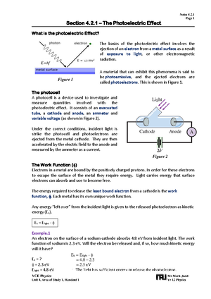
Photoelectric effect
IMPORTANT OBSERVATION
1. Existence of threshold frequency: for each metal
used at cathode there is unique frequency call
threshold frequency if frequency of light is used <
threshold frequency no photoelectrons is
emitted or released from cathode
2. Emission is instantaneous: No delay between light
shining on the cathode&photoelectrons being
produced/ It doesn’t depend on intensity of light
IMPORTANT RELATIONSHIP
1. Intensity of light independent Stopping voltage (K.E
max)
2. Intensity of light Photocurrent
3. Frequency of light was used stopping voltage (K.E
max)
4. Frequency of light was used independent
photocurrent
FLAW OF WAVE MODEL
1.Energy of the wave is dependent on amplitude, if
sufficiently intense light is used, the electrons would
absorb enough energy to escape no threshold
frequency
2.Time delay should observe, particular at low
intensities, as energy is gradually transferred to the
metal by the light waves
3. Intensity of light should be proportional to K.E max
Work function ∅=ℎ𝑓𝑜
∅1
𝑠𝑡𝑜𝑝𝑝𝑖𝑛𝑔 𝑣𝑜𝑙𝑡𝑎𝑔𝑒
This is the amount of energy required to
eject a photoelectron
If energy of photon less than this value
no photoelectron is emitted ℎ𝑓<ℎ𝑓𝑜
K.E MAX 𝐾.𝐸𝑚𝑎𝑥 =ℎ𝑓−ℎ𝑓𝑜
K.E max is stopping voltage
𝐾. 𝐸 𝑚𝑎𝑥1
𝜆
Light as Particle (Photon)
𝐸𝑝ℎ𝑜𝑡𝑜𝑛 =ℎ𝑓=𝑝𝑐=ℎ𝑐
𝜆
𝑝=𝐸𝑝ℎ𝑜𝑡𝑜𝑛
𝑐=ℎ
𝜆
𝜆=𝑐
𝑓,𝑓=𝑐
𝜆
Particles behave as Wave
𝐸𝑝𝑎𝑟𝑡𝑖𝑐𝑙𝑒 =𝑝2
2𝑚=ℎ2
2𝑚𝜆2=1
2𝑚𝑣2
𝜆=ℎ
𝑝=ℎ
𝑚𝑣=ℎ
√2𝑚𝐸
Only moving particle behave as wave
Electron diffraction pattern
IF photon and beam of electron pass through
a crystal sample
produce same wavelength
produce same momentum
same fringe spacing
Energy of electron different from energy of
photon
Single Photon/Young’s Double slit
When the light source so weak (intensity is
too low) we can conclude only one photon
was passing through a slit
after long tome light&dark bands patter
appear
evidence for Wave-particle duality
Einstein&Photonelectric effect
Light travelled in discrete packets of energy
and defined intensity as number of
photon(N)
𝑁= 𝑒𝑛𝑒𝑟𝑔𝑦 𝑜𝑓 𝑙𝑖𝑔ℎ𝑡 𝑏𝑒𝑎𝑚
𝑒𝑛𝑒𝑟𝑔𝑦 𝑜𝑓 𝑝ℎ𝑜𝑡𝑜𝑛 (ℎ𝑓)
Adsorption&Emission
∆𝐄=𝐡𝐟=𝐡𝐜
𝛌
Energy level
Eemission=Eintial-Efinal
Eg from energy level n=3 to ground state
It will be 2 possible ways: n=3 to n=2 and n=2 to n=1.
Eabsorption=Efinal-Eintial
Electrons exist in discrete energy levels, for emission, when
electron moves to lower level it release a photon with energy
exactly equal to the difference between energy levels of
atom. For absorption, when a photon/light go to an atom, an
electron will absorb an energy from photon, this energy
equal to energy levels between ground state and higher
state.
Emission spectra dark and some colour/Absorption spectra: colour and
some dark
Uncertainty principle&Single slit
diffraction
-Uncertainty in position is inversely proportional
to uncertainty in momentum
-Increasing the slit width, increase the positional
uncertainty, decreases the uncertainty of the
momentum of the particles decrease in the
extent of diffraction on the screen (Less
diffraction).
Standing waves of electron
According to de Broglie’s model of atom.
Electrons are modelled as standing waves
around the nucleus. Their wavelengths are
restricted to discrete values fit as only certain
wavelengths will support standing waves.
(Wavelength must be whole number to keep it
orbiting in stable 2πr=n 𝛌 Discrete wavelengths
mean discrete momenta and thus discrete
energy levels which we see as quantised energy
states.
The reason for whole number of wavelengths is
to avoid destructive interference with itself
Practical
Independent: controlled by experimenter (x-axis)
Dependent: outcome of independent(y-axis)
Hypothesis: suggested explanation and be tested
Error: different between measured and actual value
Uncertainty: maximum different from average value of
repeated measurement
Systematic error: affect the accuracy (incorrect use of
equipment, bias) can be reduce by using calibrating
equipment (more decimal place or significant figure)
Random error: affect the reliability (measure time) can
be reduce by repeated experiment.
Average EMF
𝜺=−𝑵𝝓𝒎𝒂𝒙
𝟎.𝟐𝟓𝑷
Negative derivative of sin(x) is -
cos(x) and negative derivative of
cos(x) is sin(x)
𝑛1>𝑛2
1eV=1V
eV –> J : x1.6x10^-19
J eV: :1.6x10^-19