- Information
- AI Chat
Completed FL2020 12.9.2 Lab - Configure IPv6 Addresses on Network Devices
Network Components (IST 1224)
Hinds Community College

Preview text
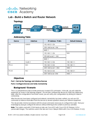
Topology
Addressing Table
Device Interface IPv6 Address Prefix Length Default Gateway
R1 G0/0/0 2001:db8:acad:a::1 64 N/A
R1 G0/0/1 2001:db8:acad:1::1 64 N/A S
PC-A NIC 2001:db8:acad:1::3 64 fe80::
PC-B NIC 2001:db8:acad:a::3 64 fe80::
Objectives
Part 1: Set Up Topology and Configure Basic Router and Switch Settings
Part 2: Configure IPv6 Addresses Manually
Part 3: Verify End-to-End Connectivity
Background / Scenario
In this lab, you will configure hosts and device interfaces with IPv6 addresses. You will issue show commands to view IPv6 unicast addresses. You will also verify end-to-end connectivity using ping and traceroute commands.
Required Resources
1 Router (Cisco 4221 with Cisco IOS XE Release 16.9 universal image or comparable) 1 Switch (Cisco 2960 with Cisco IOS Release 15(2) lanbasek9 image or comparable)
2 PCs (Windows with terminal emulation program, such as Tera Term)
Console cables to configure the Cisco IOS devices via the console ports
Ethernet cables as shown in the topology
Note : The Gigabit Ethernet interfaces on Cisco 4221 routers are autosensing and an Ethernet straight- through cable may be used between the router and PC-B. If using another model Cisco router, it may be necessary to use an Ethernet crossover cable.
Instructions
Part 1: Cable the Network and Configure Basic Router and Switch Settings
After cabling the network, labeling the devices with the correct names on the diagram, and initializing and reloading the router and switch, complete the following:
Step 1: Configure the router.
Assign the hostname and configure basic device settings including security settings (use Cisco and Class for passwords)..
Step 2: Configure the switch.
Assign the hostname and configure basic device settings including security settings (use Cisco and Class for passwords).
Part 2: Configure IPv6 Addresses Manually
Step 1: Assign the IPv6 addresses to Ethernet interfaces on R1.
a. Assign the IPv6 global unicast addresses, listed in the Addressing Table, to both Ethernet interfaces on
Open configuration window R1.
b. Verify that the correct IPv6 unicast address is assigned to each interface.
What link-local address is currently assigned to each interface?
Note : The link-local address (fe80::) displayed is based on EUI-64 addressing, which automatically uses the interface Media Access Control (MAC) address to create a 128-bit IPv6 link-local address.
c. To get the link-local address to match the global unicast address on the interface, manually enter the link- local addresses on each of the Ethernet interfaces on R1 fe80::1 as the link-local address.
Note : Each router interface belongs to a separate network. Packets with a link-local address never leave the local network; therefore, you can use the same link-local address on both interfaces.
Close a configuration window d. Use a command of your choice to verify that the link-local address has been changed to fe80::1. Question: Which two multicast groups have been assigned to interface G0/0/0?
Type your answers here.
Step 2: Enable IPv6 routing on R1.
a. On a PC-B command prompt, enter the ipconfig command to examine IPv6 address information assigned to the PC interface. Question: Has an IPv6 unicast address been assigned to the network interface card (NIC) on PC-B? No – I set it to Fe80::1 because the PC’s are using the link local address fe80::1 as the default gateway
Type your answers here.
Open configuration window b. Enable IPv6 routing on R1 using the IPv6 unicast-routing command.
c. Use a command to verify the new multicast group are assigned to interface G0/0/0. Notice that the all- router multicast group (FF02::2) now appears for interface G0/0/0.
What joined group addresses are listed as well? A second address
From PC-B, ping the link-local address for G0/0/0 on R1.
Note : If end-to-end connectivity is not established, troubleshoot your IPv6 address assignments to verify that you entered the addresses correctly on all devices.
Reflection Questions
- Why can the same link-local address, fe80::1, be assigned to both Ethernet interfaces on R1?
packets never leave the local network, so the same link-local address can be used on an interface associated to a different local network.
- What is the Subnet ID of the IPv6 unicast address 2001:db8:acad::aaaa:1234/64?
2001:db8:acad ere.
Router Interface Summary Table
Router Model Ethernet Interface #1 Ethernet Interface # 2 Serial Interface #1 Serial Interface #
1800
Fast Ethernet 0/ (F0/0)
Fast Ethernet 0/ (F0/1) Serial 0/0/0 (S0/0/0) Serial 0/0/1 (S0/0/1)
1900
Gigabit Ethernet 0/ (G0/0)
Gigabit Ethernet 0/ (G0/1) Serial 0/0/0 (S0/0/0) Serial 0/0/1 (S0/0/1)
2801
Fast Ethernet 0/ (F0/0)
Fast Ethernet 0/ (F0/1) Serial 0/1/0 (S0/1/0) Serial 0/1/1 (S0/1/1)
2811
Fast Ethernet 0/ (F0/0)
Fast Ethernet 0/ (F0/1) Serial 0/0/0 (S0/0/0) Serial 0/0/1 (S0/0/1)
2900
Gigabit Ethernet 0/ (G0/0)
Gigabit Ethernet 0/ (G0/1) Serial 0/0/0 (S0/0/0) Serial 0/0/1 (S0/0/1)
4221
Gigabit Ethernet 0/0/ (G0/0/0)
Gigabit Ethernet 0/0/ (G0/0/1) Serial 0/1/0 (S0/1/0) Serial 0/1/1 (S0/1/1)
4300
Gigabit Ethernet 0/0/ (G0/0/0)
Gigabit Ethernet 0/0/ (G0/0/1) Serial 0/1/0 (S0/1/0) Serial 0/1/1 (S0/1/1)
Note : To find out how the router is configured, look at the interfaces to identify the type of router and how many interfaces the router has. There is no way to effectively list all the combinations of configurations for each router class. This table includes identifiers for the possible combinations of Ethernet and Serial interfaces in the device. The table does not include any other type of interface, even though a specific router may contain one. An example of this might be an ISDN BRI interface. The string in parenthesis is the legal abbreviation that can be used in Cisco IOS commands to represent the interface. End of document
Completed FL2020 12.9.2 Lab - Configure IPv6 Addresses on Network Devices
Course: Network Components (IST 1224)
University: Hinds Community College