- Information
- AI Chat
Road Construction Materials Basic Knowledge
Bsc.Civil Engineering (ENC211)

Related Studylists
MJoMba💫💫✨🌟✅Preview text
J. Kisunge
Road Construction
Materials
Basic Knowledge and Test Procedures
J. Kisunge
January 2012
Road Construction
Materials
Basic Knowledge and Test Procedures
i
Road construction
Geological map of Tanzania
Foreword
This Guide is a refined edition of the Road Construction Materials (Fundamental Tests, Formulae and Terminology) issued in March 2003 as a draft for sharpening the knowledge of laboratory personnel (young engineers and technicians) who are responsible for the quality control of the roadbuilding materials. Due to economic growth and rapid development in Tanzania, the government has been boosting the road budget yearly, resulting in many road projects in the country at a time; hence, expanding job market for the local highway engineers. However, competency in highway technology (especially materials) has been impeding most engineers from the market. As the roads construction boosted up in the country in 90’s, most of the local highway engineers were still at colleges and universities for their studies, while the graduate engineers had no experience in highway engineering for lack of training sites. Therefore, the past few years of road constructions have been a transition period for most graduate engineers to acquire field experience. However, Tanzanian is a large territory with variable geology and topography, therefore, the field of practice for a highway engineer is so broad to cover, otherwise the experience mounted up by most engineers might be of similar nature (alike design standards, identical specifications, similar materials and environments), which does not build professionalism. A highway engineer who has gained most of his/her field experience in one part of the country loses self-confidence when he/she goes to another part of the country with different types of materials and environment. For instance, a materials engineer who is used to deal with the natural gravels stares when he/she faces stabilization process. This happens also to an engineer who has spent most of his/her time on the surface treatments when gets involved in asphalt technology. Despite the modern technological materials, the local highway and material engineers need enough time to master the country topography and geology before declaring their experiences.
ii
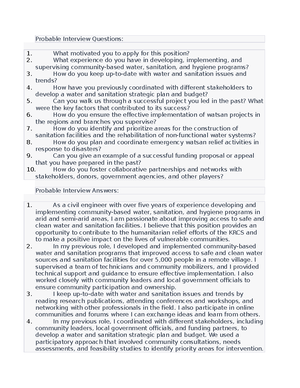
Some types of local Gravels
For instance, they are supposed to understand the behavior and performance of lateritic gravels and granite rocks found in the Lake zone, quartzitic gravels and gneiss rocks in the Central zone, coral gravels and limestone in the Coast regions, scoria and basalt found in the volcanic regions (e. Kilimanjaro, Arusha and Mbeya) and so on, instead of jumping into a complex design or applications of the imported materials that might be costly or environmentally non-compliant. The material engineers should bear in mind that, the right judgment on materials quality comes through broad understanding of the materials behavior, rather than just comparing test results with the specification figures. That is in view of the fact that, an impractical material engineer may let marginal materials pass just by opening his/her eyes wider on the test value than the material itself. On the other hand, he/she may not be able to consider potential modifications for the marginal materials before use or rejection, in order to facilitate the progress of the project. In general, experience is not gained through specific syllabus, but through participating in several self-contained projects, maintaining self-discipline in doing physical works, having attitude of learning from nonprofessionals and professionals; and building self-confidence. Bear in mind that, qualification is just a field of study, but professionalism comes through extensive experience. Nevertheless, experience is not the number of years spent in the field of profession, but is about what someone has gained in his/her field of profession. This Guide is intended therefore, to assist the material engineers and other quality control personnel (e. laboratory technicians, work supervisors, etc.) with concise knowledge about highway materials and their applications. It is giving important tips (definitions, main points and illustrations) and the outlined procedures for conducting basic tests at project level. It is therefore, a backing tool for the materials practitioners.
J. Kisunge
iv
- Soil Materials...............................................................
- Grading...........................................................................
- Atterberg limits...............................................................
- Proctor.............................................................................
- CBR..................................................................................
- Field density....................................................................
- DCP Test.........................................................................
- Specific gravity...............................................................
- Asphalt Materials.....................................................
- Bitumen...........................................................................
- Mix Design......................................................................
- Immersion Index............................................................
- Surface Treatment..................................................
- Binder...............................................................................
- Chipping..........................................................................
- Application rates............................................................
- Site application...............................................................
- References......................................................................
- Appendices....................................................................
- Appendix 1: Simple but Confusing terms.......................
- Appendix 2: Road Terminology.......................................
- Appendix 3: Pictorial description of Road terms..........
- Appendix 4: Sieve Standards.............................................
1
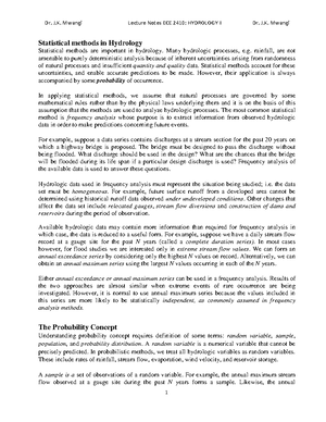
Traffic Over-loading
Pavement Rutting
Pavement Cracks
Chapter 1
Introduction
Although majority of the road failures are normally reported as outcome of traffic over-loading and environmental influences, distress investigations reveal that most of the road failures in Tanzania develop prematurely due to the use of substandard materials and poor construction techniques rather than over- loading and environmental influences. This brings views that, for a road project to achieve quality product that would fulfil the functional and structural requirement with high degree of confidence it must have appropriate and effective quality system, which screens out substandard materials and put a stop to poor construction techniques. In order to be appropriate and effective, quality system should comprise the knowledgeable staff, proper testing plan and equipment. It should also focus on the materials quality before being used to a permanent work and monitor closely the processing and finishing techniques. Durability of pavement is not judged instantly by the appearance of final product, but is guaranteed by proper design, good quality of materials and proper construction techniques. Specifications alone are not enough to produce a durable road if quality of the applicable materials is not accurately revealed and cared for. Quality control requires not only a good knowledge of materials characteristics, but also being confident in handling and testing the materials, correct interpretation of the test results, timely delivery of the test results and familiarity with the construction techniques. However there are many written books and standard specifications, which describe the characteristics of road construction materials, most of them are based on the European and American practices and environments. Such books do not focus much on the Tanzanian materials, which may fail to meet the overseas specifications but perform satisfactorily in the local environments. Therefore, it is the responsibility of local engineers to write down their experiences on the performance of local materials and set the best practices of treating such materials.
3
Protective Gears
Some basic principles to be obeyed when working in materials laboratory are:
- Think before you do (make right judgement before you take action).
- Use protective gears (gloves, aprons, etc.) when handling hot materials or chemicals.
- Deal with hot materials or dangerous chemicals at a designated place, avoid hazardous environment.
- Do not litter waste materials or spill liquids on the floor (may cause accident).
- Do not handle materials or equipment in a way that may cause accident or injury.
- Ask for assistance in case of handling heavy objects.
- Do not switch on or work with electrical apparatus with wet hands.
- Do not use a device or machine that you do not know how to operate.
- Follow the instruction manuals provided by the manufactures for operating the machines or other testing devices.
- Inspect the testing equipment before using it (make sure that it is properly assembled and its parts are perfect).
- Make sure the testing environment is free from congestion and interference from other operations (e. vibrations, vapour, heat, etc.)
- Obey the nature of each device and use it for its intended use only (do not overload machine or balance; or put plastic devices in oven, etc.)
- Make sure the testing machine is free and the power put ‘off’ after testing (do not leave a machine ‘on’ or any weight on the balance).
- Put equipments in the right place after testing (do not combine glassware or plastic apparatus with metallic equipment).
- Be clean and leave the laboratory tidy after testing.
4
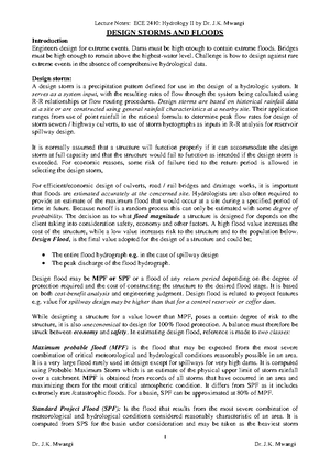
Figure 1: Typical laboratory arrangement
Sample preparation area
Asphalt
Room
Cold Room
Auto Compactor Compaction Plinth
Wooden Bench (with cabinet) CBR Tester
Marshall Tester
Oven
Sample storage area
Toilet
Technicians’ Room
Lab In-charge
Curing Tanks
Cores capping bench
Compression Machine
SG Frame
Store Room
Toilet LAA
6
Sample Splitter
Grading Sieves
- Grading
Grading test is also known as sieve analysis or particle size distribution. The test reveals the proportions of different particle sizes in a granular material (e. aggregate, soil, etc.) by passing a sample on a range of sieve sizes. A dry sample is passed on the sieves either without washing (known as dry sieving) or after soaking and washing the sample over 0 sieve to diffuse the sticking particles prior to sieving (known as wet sieving). Dry sieving is used for cohesionless (non-plastic) materials like sand and aggregate; while wet sieving is preferred for cohesive materials like soil and fillers. Some terms encountered in the grading test are; Sieve:- wire-cloth or square-mesh with apertures (openings) of definite dimensions nested on a brass or stainless steel frame. Quartering:- the process of obtaining a small representative quantity of sample by dividing a large quantity of material into quarters (four nearly equal parts) and combining the two opposite parts (as shown below), then dividing the combined parts several rounds until a small representative quantity is obtained.
Riffling:- the process of obtaining a small representative quantity of sample by dividing a large quantity of material using a riffle box or sample splitter (containing alternating slots), which divide the material into two equal parts. Then, one of the obtained two parts is poured again into the slots until the desired quantity is obtained.
Test procedure: a) Dry Sieving: 1) Obtain a test sample by quartering or riffling the material. 2) Dry the sample in oven (at 105 – 110 0 C) and allow it to cool. 3) Record the weight of test sample after cooling (m1). 4) Arrange the specified sieves with a receiver at the bottom side. 5) Pour sample in the topmost sieve and cover it, then shake the sieves until no more material passes through each sieve. 6) Weigh (either individually or cumulatively) the material retained on each sieve (m2).
Step 1 Step 2 Step 3 Step 4 Sample
7
Retained particles
b) Wet Sieving: 1) Obtain a test sample by quartering or riffling the material. 2) Dry the sample in oven (at 105 - 110 0 C) and then allow it to cool to a room temperature. 3) Determine the weight of the test sample after cooling (m1). 4) Wash the sample on a 0 sieve (place 1 or 2 sieve on top of the 0 sieve to protect the wire cloth from tearing). 5) Dry the washed sample in oven for at least 12 hours. 6) Arrange the specified series of sieves with a receiver at the bottom side. 7) Pour sample in the topmost sieve and cover it with the lid (if the sample is too large, then pour a little quantity at a time). 8) Shake all sieves (by hand or a mechanical shaker) until no more material passes through each sieve. 9) Determine the weight (individually or cumulatively) of the material retained on each sieve (m2). Note: Cumulative weights provide the percentage of particles retained on the sieves progressively, while individual weights provide the percentage retained on an individual sieve (does not follow the sieve sequence).
Calculations:
Cumulative percentage retained on each sieve: % retained = m2 x 100 m
Cumulative percentage passing on each sieve: % passing = 100 – % retained
Fineness modulus (FM): (Calculated for fine aggregates used for concrete, the applicable sieves are 4, 2, 1, 0, 0 and 0). FM = Sum of the cumulative %retained on the sieves 100
Coefficient of uniformity (the ratio of d 60 to d 10 ):
Cu = d 60 (The sieve size at which 60% of the material passes) d 10 (The sieve size at which 10% of the material passes)
9
Flaky particles
Thickness Gauge
Passing particle through the Gauge
- Shape test Shape tests comprise flakiness index (FI) and elongation index (EI). The indices obtained in both tests reveal the dimensions of aggregate particles, as some particles are normally cubic while others are flaky or elongated.
a) Flakiness index (FI) Flaky particles are the particles whose thicknesses are less than 0. of their mean size (e. mean size of 14–10mm fraction is 12mm, therefore, thickness of flaky particle is less than 0 x 12 = 7). The test is carried out on the aggregate particles of different sizes from 6 to 63mm using thickness gauge (with specific slot sizes).
Test procedure: 1) Obtain the test sample by quartering or riffling the aggregate. 2) Weigh and record the weight of the obtained sample. 3) Sieve the sample on 63, 50, 37, 28, 20, 14, 10 and 6 mm sieves and discard the sizes larger than 63 mm and smaller than 6 mm. 4) Determine the weight of particles retained on each sieve and discard the size whose weight is less than 5% of the total sample. 5) Pass each fraction through the specified slot on the gauge. 6) Determine the weight of particles passing through each slot.
Calculations:
FI = Total weight of particles passing through the slots x 100 Total weight of sample (excluding the discarded size)
Example: Aggregate fraction (mm)
Wt. of fraction (g)
Wt. Retained on the gauge (g)
Wt. Passing on the gauge (g) 63 - 50 2131 1971 159. 50 - 37 2045 1840 205. 37 - 28 1987 1748 238. 28 - 20 1875 1688 187. 20 - 14 1563 134 5 218. 14 - 10 1245 1033 211. 10 - 6 856 624 231. Total 11704. 7 1452. 7 FI = 1452 x 100 1170 4 = 12%
10
Elongated Particles
Elongation Gauge
b) Elongation index (EI) Elongated particles are the particles whose lengths are more than 1 of their mean size (i. 1 x mean size). It is carried out on the coarse particles from 6 to 50mm, using an elongation gauge having specific gaps (as shown at the bottom of illustration column).
Test procedure: 1) Obtain the test sample by quartering or riffling the aggregate. 2) Weigh and record the weight of the obtained sample. 3) Sieve the sample on 50, 37, 28, 20, 14, 10 and 6 mm sieves and discard the particles larger than 50 mm and smaller than 6 mm. 4) Determine the weight of particles retained on each sieve and discard the size whose weight is less than 5% of the total sample. 5) Pass each fraction through the specified gap on the elongation gauge. 6) Weigh the particles that do not pass through the designated gaps (i. elongated particles).
Calculations:
EI = Total weight of the retaining particles x 100 Total weight of sample (excluding the discarded size)
Example:
Aggregate fraction (mm)
Wt. of fraction (g)
Wt. Retained on the gauge (g)
Wt. Passing on the gauge (g) 50 - 37 1988 488 1499. 37 - 28 1869 198 1671. 28 - 20 1754 221 1532. 20 - 14 1331 111 1219. 14 - 10 1051 317 734. 10 - 6 961 105 856. Total 8957. 3 1443. 0
Elongation Index = 14 43 x 1008957 = 16%
12
TFV Test Set
Compression Machine
- Ten percent Fines Value (TFV) TFV test also measures the resistance of aggregate to crushing. It is also conducted on the 14 – 10mm fraction as for the ACV test, however, the TFV is preferred for weak aggregates in order to overcome the cushioning effect of excessive fines that might be produced by the ACV test. The test is carried out on a dry or soaked aggregate sample.
Test procedure: 1) Sieve the aggregate on 14mm and 10mm sieves as for the ACV. 2) Fill the ACV mould with three layers of fraction retained on 10mm sieve and strike each layer with 25 strokes of tamping rod. 3) Level the material and insert the crushing plunger in the mould. 4) Place the mould (with sample and plunger) on the platen of the concrete compression machine. 5) Apply a certain force so as to cause penetration of 20mm on the materials surface in 10 minutes and record it (f). 6) After 10 minutes, release the force, pour material in a clean tray and determine its weight (m1). 7) Sieve the whole material on 2 sieve. 8) Weigh the material retained on 2 sieve (m2).
Calculations: Weight of material passing 2 = m1 – m % passing 2 sieve (M) = (m1 – m2) x 100 m TFV = 14 f M + 4 Where; M = the percentage passing 2 sieve (ranging 7% – 12%; if not, then prepare and test another sample with adjusted force until the value obtained falls within the mentioned range). f = the force that caused penetration of 20mm.
Alternatively;
- Carry out the ACV test with 50KN, 100KN, 150KN and 400KN.
- Plot the results on a chart with forces on x-axis and the percentage passing 2 on y-axis.
- Join the points with the best-fit curve and read off the force corresponding with 10 % passing 2 sieve as the TFV.
13
AIV Apparatus
Dropping the hammer
- Aggregate Impact Value (AIV)
The AIV test is used to measure resistance of aggregate to impact.
It is commonly carried out on the 14 – 10mm fraction; however,
20 – 14mm or 10 – 6 fractions also may be used. The chosen
fraction can be tested in a dry condition or soaked condition.
Test procedure:
- Obtain the required fraction by sieving aggregate on the specified sieves (e. 20 – 14mm, 14 – 10mm or 10 – 6).
- Fix sample cup on the base plate of the AIV frame.
- Fill aggregate in the cup to overflow and tamp it with 25 strokes of the tamping rod.
- Level the surface by rolling the tamping rod over the cup (remove any projecting particles and fill depressions by hand).
- Apply 15 blows of the AIV hammer on the aggregate surface.
- Remove the mould and place it in a clean tray, then remove the sample by hammering gently on the outside of the cup.
- Brush the cup in the tray and take the weight of the sample (m1).
- Sieve the sample on 2 for 14 – 10 fraction (or on 3 for 20 – 14 fraction and on 1 for 10 – 6 fraction).
- Weigh the material retained on the separating sieve (m2).
Calculations: Material passing the separating sieve = m1– m AIV = (m1– m2) x 100 m Note: The AIV of weak aggregates might mislead, especially if fines produced are more than 20%. Therefore, it is recommended to apply fewer blows (say 8, 10 or 12) and a Modified Aggregate Impact Value (MAIV) calculated as follows:
- MAIV = % fines x 15 Applied number of blows
Example: Sample no. 1 2 3 Average Total weight of sample (m1) 47 1 457 .2 45 9. Wt. Retained on the sieve (m2) 358 344 344. Wt. Passing separation sieve (p) 113 112 115. AIV = (p x 100)/m1 24 .0 24 25 24.
[*Introduced by Hosking and Tubey]
Road Construction Materials Basic Knowledge
Course: Bsc.Civil Engineering (ENC211)

- Discover more from: